Reinforcement and stability: at the heart of structural safety

Ferraillage - Ecluse Royer - greisch

What is reinforcement design?

Reinforcement design relates to all the steel reinforcement elements integrated into concrete to give it the tensile strength it naturally lacks. Based on stability calculation assumptions, this design process operationally turns the requirements of the standards (Eurocodes, national or client-specific requirements) into construction-ready drawings and construction specifications. Reinforcement design involves more than just the sizing of bars: it determines the bearing capacity, service behaviour (deformations, controlled cracking), the durability (cover, quality of anchorages, protection in aggressive environments) and the resilience of the structures when subjected to extreme stresses (earthquake, fatigue, impact, fire). This makes it the critical interface between the theoretical design and the reality on the construction site: the geometry of the bars, their continuity, management of overlaps and connections with other materials (pre-stresses, metal inserts, equipment anchorages) have an impact on the structure’s overall performance. Based on a multidisciplinary approach, like the one adopted by Bureau greisch, reinforcement design becomes a driver of optimisation, cost control and long-term reliability, by integrating from the outset the constraints imposed by the structure’s production, construction and future maintenance.

What are the different types of reinforcement detailing?

The types of reinforcement detailing mainly differ in terms of their structural function and their behaviour within reinforced concrete. Firstly, there are longitudinal reinforcement elements, which are responsible for resisting tensile and bending forces (main bars in beams, top and bottom mats in slabs, tensile steel elements in walls and footings). They are supplemented by transverse or shear reinforcement elements (stirrups, bent bars, closed ties, inclined bars), designed to control shear forces and punching shear, particularly around supports and in load concentration areas. In addition to these structural reinforcements, there are distribution and crack-control reinforcements, arranged perpendicularly or in secondary mats to homogenise the concrete’s behaviour, distribute stresses more evenly and limit crack widths under service conditions. Depending on the type of structure, Bureau greisch can also implement specific reinforcement elements: three-dimensional cages for prefabricated elements, tie‑beams and perimeter ties to ensure overall stability, reinforcements anchored into inserts or plates used to connect with metal structures, as well as special arrangements for seismic zones (confined anchorage blocks, hoops, joint reinforcements). The combination of these different types of reinforcement detailing makes it possible to guarantee the ULS capacity, ductility, durability and overall resilience of the structures designed by Bureau greisch.

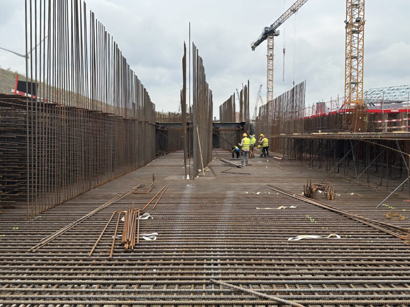
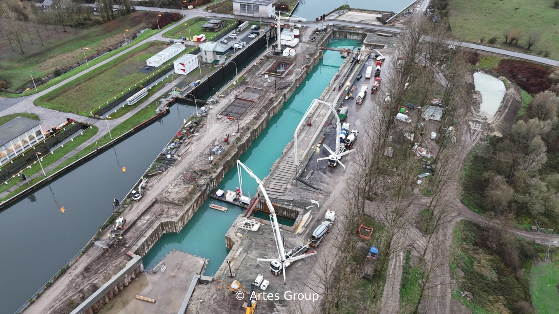
In the structure of the Obourg lock, the transverse reinforcement makes it possible to resist in particular the lateral pressure exerted by 10m of earth when the lock chamber is empty. Longitudinally, reinforcement detailing makes it possible to contain the width of cracks caused by shrinkage. In actual fact, the 150 metres of the lock chamber are built without expansion joints. At the lock heads, all the forces being exerted from the feet of the gantry must pass through to the concrete. Locally, reinforcement is provided to prevent concrete failure and to ensure the stability of the gantry operating the gate.

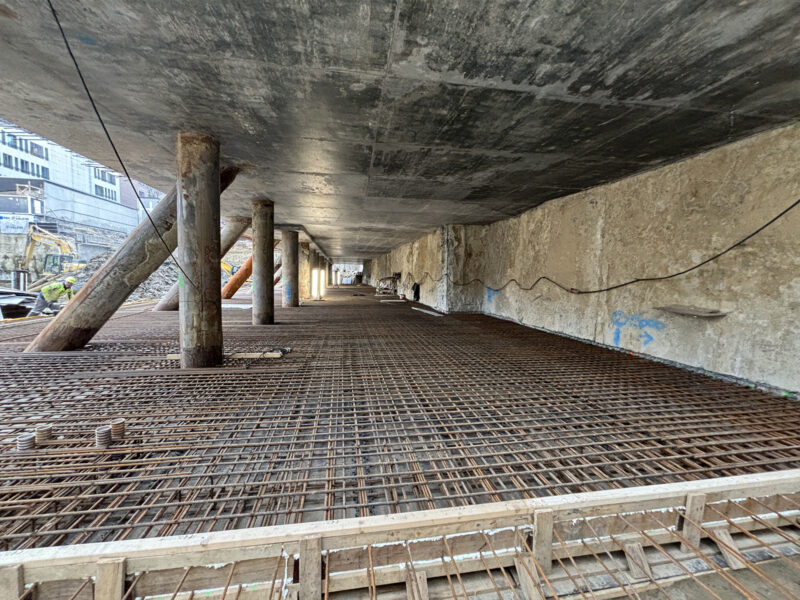
During the temporary phase, a reinforced concrete element was produced under water to transfer the uplift forces from the groundwater table to the vertical tie-downs. Due to the lack of visibility, a reinforcement element was designed that could be installed like Lego blocks by divers. All the installation tolerances were considered in order to ensure compliance with the required lap lengths.

An integrated approach to stability and reinforcement

According to an integrated engineering approach, overall stability and reinforcement design are never treated as two separate, sequential disciplines, but as a single, iterative and interconnected system. Structural engineers, designers of special structures and modellers collaborate from the first load-assumption stage to simultaneously refine the structural configuration (static scheme, span selection, continuity strategy, horizontal reinforcement devices) and the reinforcement strategy (density, bar hierarchy, ductile zones, redundancies). This early integration process makes it possible to anticipate force concentrations, to adjust the geometry of load-bearing elements and to identify critical nodes that will require enhanced reinforcement or special confinement, particularly for seismic zones, complex transitions or concrete-steel interfaces. The numerical stability models (2D/3D, non-linear analyses, time-dependent effects) feed directly into the detailed reinforcement models, ensuring consistency between the calculation assumptions, geometric tolerances and construction sequences. Conversely, feedback from reinforcement design – bending feasibility, density limitations, accessibility for concreting or vibration – can lead to recalibration of the load-bearing schemes in order to maintain an optimal balance between resilience, constructability and an efficient use of steel quantities. This joint approach, applied to complex buildings as well as bridges, transport infrastructure and hydraulic structures, produces structures that are more efficient, better controlled during the construction phase and more resilient throughout their life cycle.
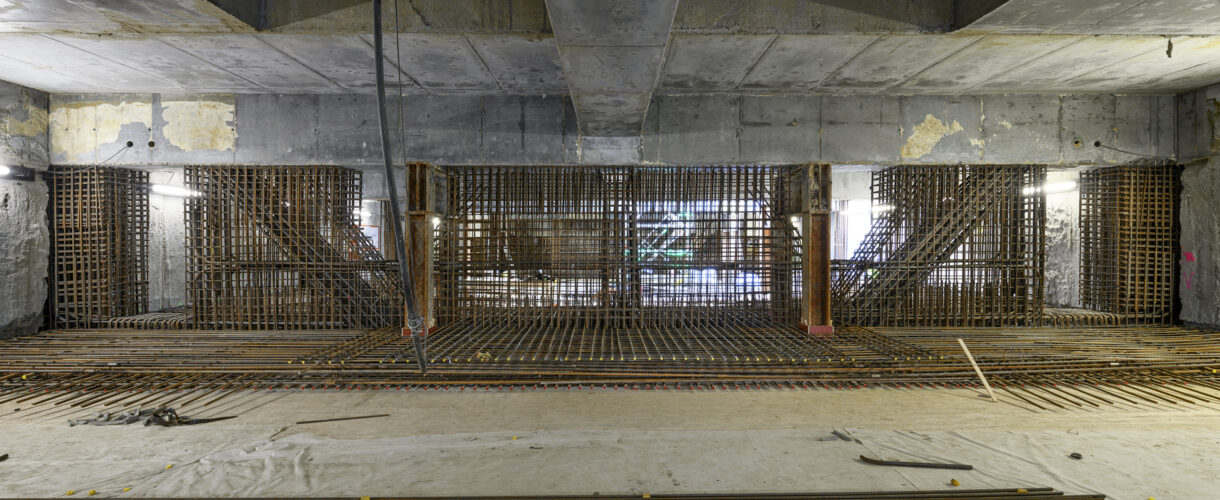
Take the example of the Realex project, a building including a conference centre for the European Commission as well as offices: the raft foundation must resist an uplift pressure equivalent to 7 m of water. As a result, it is reinforced so that loads are transferred towards the vertical load‑bearing elements (or, locally, towards tension‑designed piles). The reinforcement detailing is also designed to compensate for any differential settlements resulting from the very different workloads carried by the two types of piles used in the deep foundations.

From design to execution detailing

From design to execution detailing, Bureau greisch creates a continuous methodological workflow that links advanced structural calculations, BIM modelling and the production of reinforcement drawings that can be used directly by contractors. From the study’s initial phases, the analytical models (2D/3D, dynamic analyses, seismic combinations, fatigue checks) are configured to generate load sets consistent with future construction sequences, possible tensioning procedures and temporary conditions (shoring, removal of shoring, provisional prestressing). These models are then used to populate integrated numerical models, providing the precise definition of all the execution details: special construction arrangements for dissipative areas, reinforcement continuity across multiple supports, connection reinforcement between successive concrete pours, openings for inserts and equipment anchorages, as well as lap-splice strategies adapted to pour sequences and accessibility constraints. The plans produced (reinforcement drawings, exploded views, node sections, bar bending schedules) are systematically coordinated with the formwork plans, the technical work packages and the metal-concrete interfaces, allowing a significant reduction in unexpected on-site issues, last-minute adaptations and overconsumption of steel. This approach, which applies to complex buildings, as well as transport infrastructure, hydraulic structures or special structures, ensures full traceability between calculation assumptions, design decisions and implemented specifications, while providing clients and contractors with a reliable basis for planning, prefabrication and ensuring optimal lead times.

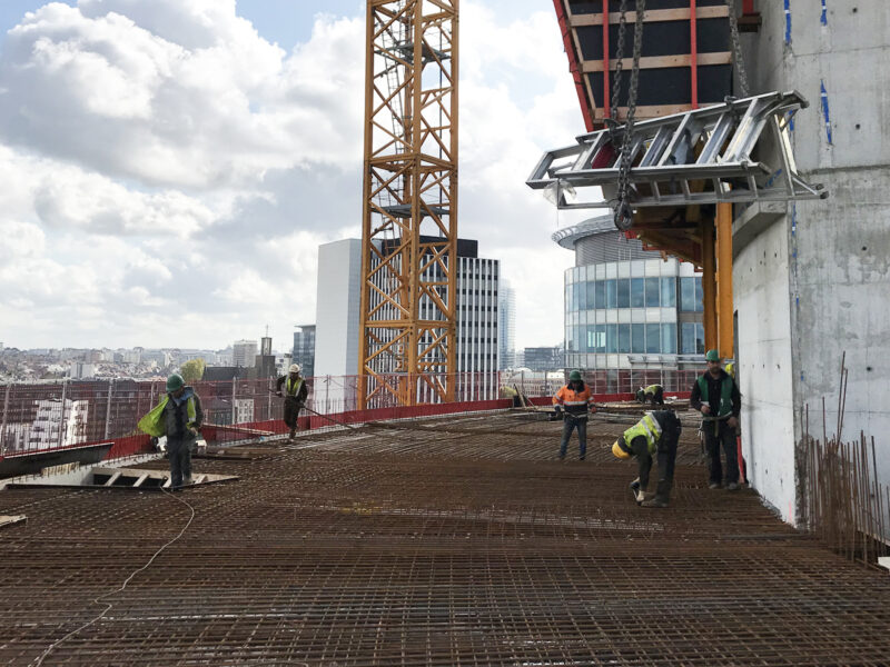
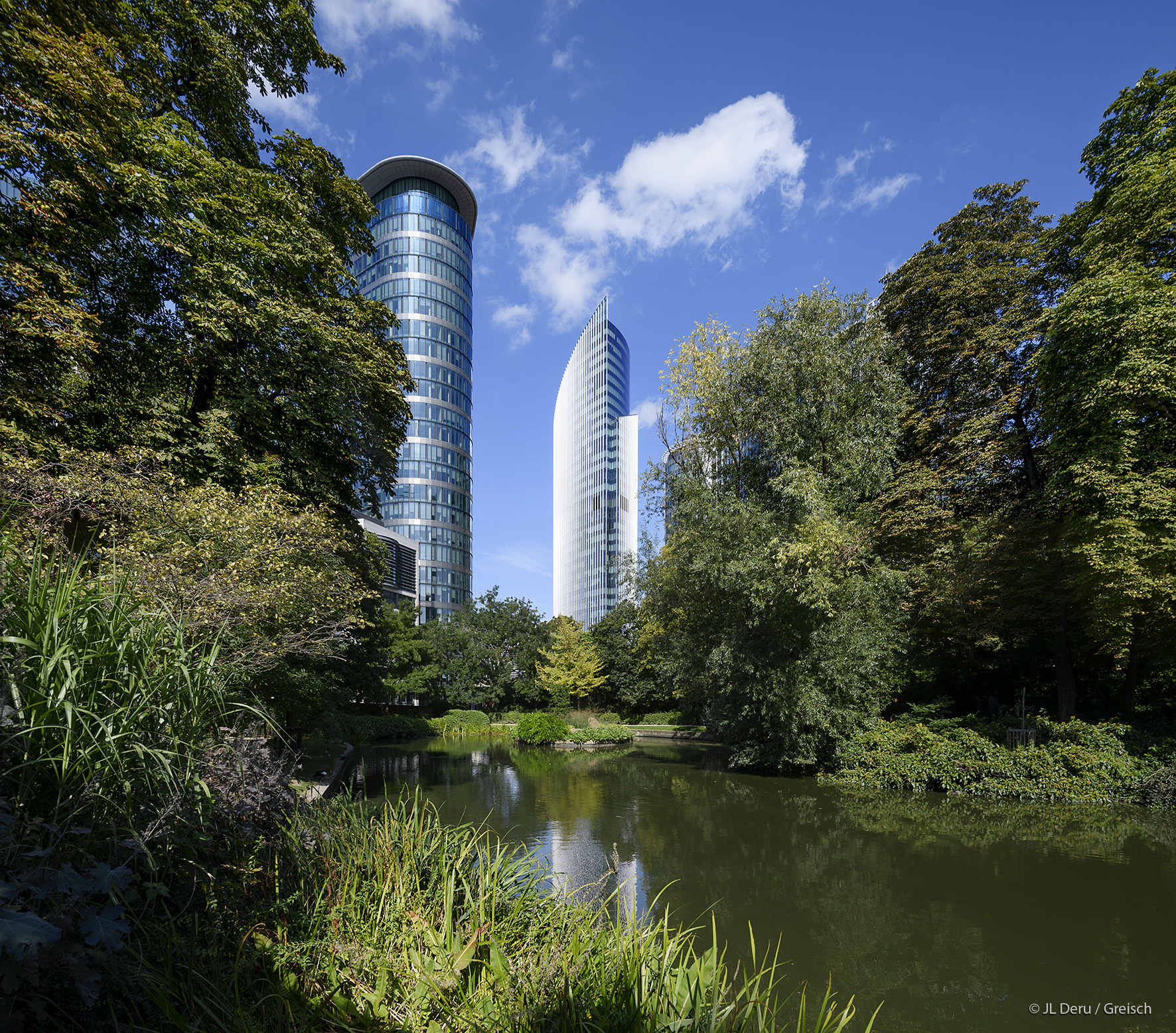
In the case of the “Iris Tower” project, its geometry has been determined by both spatial constraints — linked in particular to a very small footprint — and a strong architectural design intent. These two factors have resulted in very specific structural configurations that were analysed from the earliest design stages in order to guarantee their feasibility during the construction phase. One of the particular features of this project is significant load deviations. These are achieved in different ways, including the construction of inclined columns on the ground floor, load deviations in the basements to maximise the space available for the car park, as well as the presence of Y-shaped columns on the upper floors. These features make it possible to achieve the specific stepped geometry of the façade on the upper floors. Particular attention was focused on analysing the constructive nodes to ensure that they were large enough and had the right dimensions for implementing the reinforcement detailing, thereby guaranteeing the proper execution of the structural elements.

Solutions tailored to every type of structure

Bureau greisch develops differentiated reinforcement strategies for every type of structure, directly linked to functional, regulatory and operational requirements. High-rise buildings, hospitals or administrative headquarters require reinforcement elements that prioritise local ductility, continuity of load paths and the ability to reconfigure spaces, whereas bridges, viaducts and footbridges are dimensioned by integrating fatigue effects, differential creep and sequential construction phases (successive launches, incremental pushing, cantilevers). In the case of hydraulic and civil engineering structures (locks, rafts, retaining walls, tanks), the focus is on providing resistance to aggressive environments, structural waterproofing and crack control under thermo-hygrometric stresses, with reinforcement elements specifically defined for construction joints, zones of concentrated hydrostatic pressure or soil-structure interfaces. Stadiums, sporting infrastructures and special structures require complex reinforcement solutions combining large spans, unconventional geometries and combinations of dynamic loads (wind, synchronised vibrations, earthquakes), which demand advanced modelling of 3D nodes and anchorages. This finely tuned adaptation to the built environment, transport infrastructure and urban development makes it possible to offer, for each set of structures, reinforcement detailing that is high-performing and constructible, providing efficient use of steel quantities, while ensuring the traceability of technical decisions and control of the structure’s life cycle.

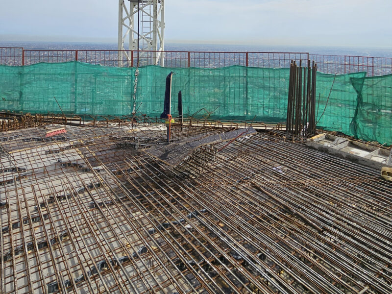
For example, Tower F in Abidjan has, because of its sheer size, several structural elements with particularly large dimensions, such as core walls up to 80 cm thick, columns up to 180 cm in diameter, and a 3.5 m-thick foundation raft. In light of this, it is particularly important to take into account the construction sequence and the delayed effects of concrete – shrinkage, creep and thermal effects. Therefore, specific reinforcement detailing has been provided in order to limit the risk of cracking in these solid elements, but also in adjacent elements, in particular floor slabs. In addition, particular attention is focused on the construction methods and on the forces likely to arise during the various construction phases. This applies in particular to the forces related to cranes, the core’s climbing formwork or collective protection devices such as wind screens.

Bureau greisch reinforcement

A rigorous production and monitoring process

In addition to producing reinforcement drawings, Bureau greisch follows a structured production and monitoring process based on internal cross-checking protocols, checklists and systematic traceability of technical decisions. Every deliverable – reinforcement drawings, node extracts, bar bending schedules – is subject to an independent review cycle, including validation of the calculation assumptions, compliance with Eurocodes and the client’s specific requirements, as well as ensuring compatibility with formwork, prefabrication and possible tensioning stresses. This process goes hand in hand with rigorous version control, ensuring consistency between digital models, paper-based drawings and files exchanged with the contractors involved, thereby limiting the risk of discrepancies during construction. During the construction phase, feedback from the field (concerning non-conformities, local adaptations, unexpected geotechnical or architectural issues) is integrated into a formalised plan review workflow, making it possible to quickly update reinforcement details while maintaining the full history of the modifications made and the reasons for them. This arrangement, combined with control procedures targeting critical nodes, seismic or highly stressed areas, guarantees a high level of structural reliability and enhanced control of technical risks over the structure’s entire life cycle.

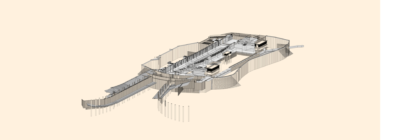
More than 700 reinforcement drawings have been produced for the Royers lock project. A dozen of them were produced entirely in 3D, specifically for areas where electromechanical components are anchored in the concrete. Thanks to these drawings, numerous conflicts and problems could already be resolved in the design phase, contributing to the smooth flow of construction on site.

Strakon Ferraillage - greisch

More than 25 years’ experience with STRAKON

STRAKON, its development at Bureau greisch

STRAKON was adopted by Bureau greisch as part of a gradual shift in the methods used to produce reinforcement drawings, which started in the late 1990s in response to the increasing complexity of structures and the growing number of regulatory requirements. Initially deployed as a 2D computer-aided drafting tool, STRAKON was quickly integrated into the core of the structural design workflow in order to standardise how reinforcement elements were represented, to make bar bending schedules more reliable and establish productive communication with prefabrication workshops and construction sites. Over the course of the projects implemented for engineering structures, hospital buildings, stadiums and hydraulic structures, its use has been enhanced by the development of internal libraries containing standardised detail templates, drawing templates and dedicated control procedures, ensuring both graphical and technical consistency across all deliverables. The tool has then been combined with calculation models and digital models to ensure continuity between stability analyses, construction phasing and construction-ready drawings, while integrating the specific requirements of each client (graphic standards, exchange formats, traceability requirements). This operational maturity, acquired through several decades of practical experience and continuous feedback between engineers, drafting technicians and site managers, makes STRAKON a strong link in the Bureau greisch design ecosystem, particularly suited to projects requiring a high level of detail and faultless dimensional accuracy.

Revit and its SOFiSTiK plug-in, reinforcement for BIM coordination

Thanks to Revit’s parametric environment combined with the SOFiSTiK Reinforcement plug-in, Bureau greisch can create a fully integrated BIM reinforcement workflow, extending from calculation results all the way to construction-ready deliverables. The reinforcement elements are generated on the basis of the analytical models and load combinations and then translated into intelligent 3D objects (bars, meshes, frames, mats) with detailed properties: diameters, steel grades, bending lengths, bending codes, exposure classes and phasing information. This structuring of the data facilitates precise coordination between disciplines: checking concrete cover against MEP networks, verification of clearances for inserts, openings and conduits, validation of geometric tolerances in areas with dense nodes or high concentrations of forces. Collision detection and model review tools (filtered 3D views, dynamic sections, colour coding by reinforcement type or construction phase) facilitate dialogue with contractors and prefabrication teams, while reducing the amount of rework required on site. In addition, the bidirectional link between the reinforcement objects and automatic bar bending schedules guarantees that quantities and processing lists are updated as soon as any changes are made to geometry or calculation assumptions, enhancing the traceability and reliability of the data transmitted in an advanced BIM process.

Our reinforcement projects

Take a look through our flagship projects

Feel free to reach us

Contact us